RDS-PP
Reference Designation System for Power Plants
Reference designation is a very modern and future-oriented way of plant-designation. The Reference Designation System for Power Plants – RDS-PP for short – provides the basis for object-oriented identification of individual plant components with any number of relationships to other objects.
The new identification system offers great advantages especially in the application of modern organization systems, such as operation management or maintenance systems.
Note: In the further course of the text, the term “alphanumeric” shall be used exclusively to describe characters in letter form.

Application especially in the wind energy industry
RDS-PP is mainly applied in plants of the wind energy industry – i.e. in wind power plants or wind turbines. Here in the form of the RDS-PP Application Guideline Part 32: Wind Power Plants of the professional association VGB PowerTech.
However, the system can be applied to all types of power plants and is thus explicitly not limited to wind power plants.
Standard reference and regulations
The Reference Designation System for Power Plants is a standard-based system for the designation of power plants developed by the technical association VGB PowerTech. It represents the further development of the language- and type-independent as well as cross-disciplinary Power Plant Identification System (PPS).
The history of the development of the RDS-PP
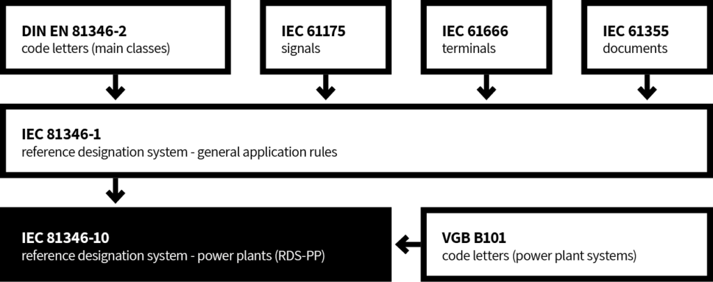
The main aim in developing the new system was to establish a reference to standards. The DIN standard 6779 entitled “Marking systematics for technical products and technical product documentation” contains the most important framework conditions for the RDS-PP. Based on this series of standards, VGB PowerTech e.V. developed the technical standard DIN 6779-10, which is specifically tailored to power plants.
The national standard was adopted by ISO (International Organization for Standardization) at the beginning of 2008 and published as an international standard under the name ISO/TS 16952-10. The IEC (International Electrotechnical Commision) had already published the IEC 61346 series of international standards for structuring and marking industrial systems, plants, equipment and industrial products in 2000. ISO/TS 16952-10 was integrated one-to-one into the IEC 81346 series in 2015 under the name IEC 81346-10.
To standardize the standards for reference marking, the organizations have agreed on a future superordinate series of standards called IEC 81346. In addition, the technical standard Reference Designation System Power Plants (RDS-PP) incorporates regulations on the designation of signals (IEC 81175), the designation of connections (IEC 81666) and the classification and marking of documents (IEC 61355).
With reference to these international standard series, the RDS-PP is a globally recognized standard for plant identification of power plants. Guideline B101 and Application Explanation B116 developed by the working groups of the VGB PowerTech e.V. technical association are also part of the RDS-PP rules and regulations. They contain the code letters for the power plant-specific system classification and, among other things, also assistance or examples for the application of the reference code system.
General description
A license plate system for power plants focuses on the following tasks:
- A unique identification of technical objects and documents.
- A classification according to purpose, task and composition.
- A mapping of the technical structures.
- A representation of interconnected relationships.
The basic principles of structuring include three different views of how to divide the various facilities. In this context, it is necessary to clarify three important questions for each individual object:
- Functional: What function does the object have or manipulate?
- Location: Where is the object located?
- Product related: What kind of object is it?
Thus, in a plant that uses the RDS-PP labeling system, there are mainly four different structure trees that are related to each other:
- The function,
- the product
- and the place
of technical objects. In addition, a tree for structuring functional relationships.
The RDS-PP offers as a labeling system with the “Functional Assignment” the possibility to establish a link between two functions. The commonalities of the structures, respectively the relations between the different trees are called role relations.
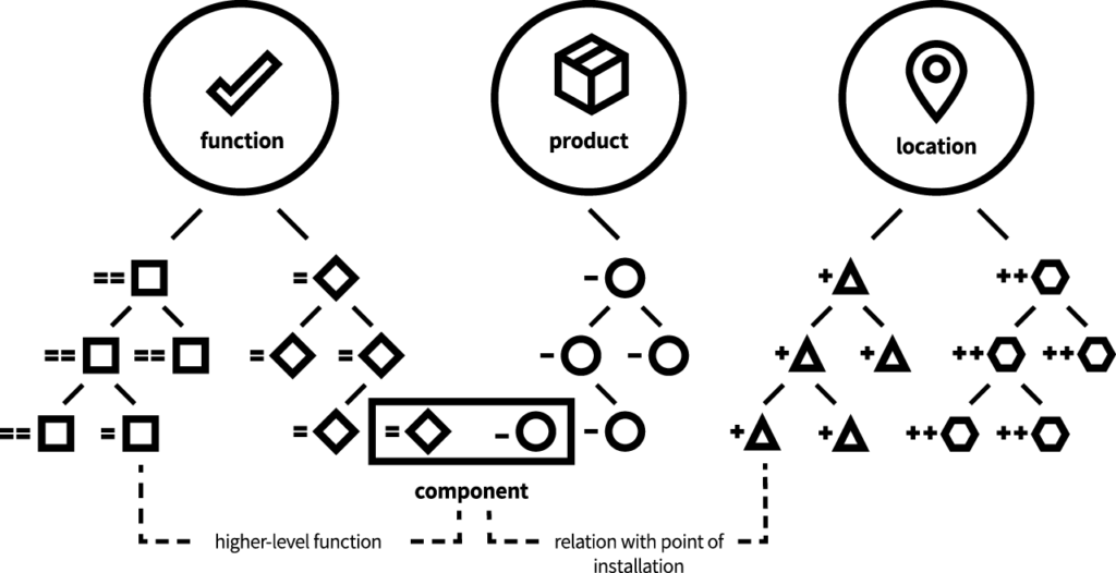
These relationships between the different considered aspects of a marked object form the core of the reference marking system. They suggest information of the component in different types of documents and products involved in the system.
In addition to the reference marking according to function, location and product aspect, the marking system RDS-PP according to IEC 81346-1 also includes a specific marking for signals, connections and documents, which is always derived from the function of the object. In addition, there is a higher-level common assignment.
The identifier of an object to be identified can thus consist of a maximum of three different parts:
- of the common assignment,
- the reference indicator,
- and a specific indicator.
Various combinations of these three components are possible in the composition of the identifier:
| Common assignment | ||
| Common assignment | Reference identifier | |
| Common assignment | Reference identifier | Specific identifiers |
| Common assignment | Specific identifiers | |
| Reference identifie | ||
| Reference identifie | Specific identifiers |
Each of the three sections of the identifier can consist of one or more so-called identifier blocks with a uniform structure.
A license plate block is divided into different outline levels containing different combinations of letters and numbers.
The smallest information unit of the indicators are the data points. They are still combined into alphanumeric and numeric sections in the respective outline levels.
The individual blocks can be identified by a specified preceding character. The following table lists the various indicator blocks with their respective prefixes and sources:
| Sign | Designation | Marking tasks / aspect | Origin of the sign, bases set in |
| # | Number | Common assignment | ISO/TS 16952-1 |
| = | Equal | Functional labeling | IEC 81346-1 |
| == | Equal-Equal | Functional labeling | ISO/TS 16952-1 |
| + | Plus | Installation type | IEC 81346-1 |
| ++ | Plus-Plus | Location | ISO/TS 16952-1 |
| – | Minus | Product related labeling | IEC 81346-1 |
| : | Colon | Connection identification | IEC 81666 |
| ; | Semicolon | Signal identification | IEC 81175 |
| & | And | Document type identification | IEC 61355 |
In addition, different license plate blocks can be combined with each other. Here, the sign furthest to the right always determines the aspect of the entire indicator.
Common assignment
For the Common Assignment section, a license plate block of the same name with a fixed structure is provided in the RDS-PP. In IEC 81346-10, two outline levels separated by a dot, each with a maximum of twelve alphanumeric or numeric data digits, are available for Common Assignment.
The block thus offers the possibility to distinguish different sites or control centers with common aspects.
The license plate block is introduced by the hash sign. The common assignment is an independent block, since it cannot be assigned to either aspect-related or specific labeling.
It represents a separate section for this reason:
| Level of detail | 1 | 3 | ||
| Section | 1….4 | 5 | ||
| Data point | # | A….N | . | A….N |
| Example | # | KW01 | . | E10 |
Reference identifier
The reference identifier section has the task of describing the object to be described according to the already mentioned three different aspects
- Function
- Location
- and Typ
to identify. A total of five different types of license plate blocks are distinguished here.
1. The function block
It is one of two function-related indicator blocks. It structures the technical objects of a plant from the point of view of the task and purpose of the components. This indicator block is made up of three different outline levels. For the higher-level distinction, a maximum of one alphanumeric and two numeric data locations are available in outline level 0. The other two outline levels each consist of combinations of five with three or two alphanumeric and two or three numeric data digits. The classification of the alphanumeric data locations is defined in outline level 1 by the VGB key B101 and in outline level 2 by IEC 81346-2.
| Outline level | 0 | 1 | 2 | |||
| Section | 0 | 1 | 2 | 3 | 4 | |
| Data point | = | AN(N) | AAA | NN | AA | NNN |
| Example | = | D0 | LAC | 10 | GP | 010 |
2. The functional assignment
It has the task of combining technical equipment of different types under a common function. For example, the mechanical parts of a pump and its electrical controls would be assigned to one function. A distinction is made between two types of functional assignment:
- The group level is used to identify functional areas and functional groups. It only includes the system identification with the outline levels 0 and 1.
- At the individual level, technical facilities are summarized more concretely in functional terms.
This indicator block consists of all three outline levels. At the group level as well as at the individual level, a third outline level separated by a dot can be added. It represents a guidance function for functional classification. In this block, too, the classification of the alphanumeric data positions of the outline levels 1, 2 and 3 must be carried out by means of the defined keys B101 and IEC 81346-2.
| Outline level | 0 | 1 | 2 | 3 | ||||
| Section | 1 | 2 | 3 | 4 | 5 | |||
| Data point | == | AN(N) | AAA | NN | AA | NNN | . | AANN |
| Example | == | D0 | MKV | 10 | GA | 010 | . | AA01 |
| Identification letter | Designation |
| AA | Reporting, monitoring |
| CA | Individual regulation |
| CB | Guidance regulation |
| HA | Operation and observation |
| MA | Direct measurementg |
| MB | Measured variable calculation |
| SA | Single control |
| SB | Group control |
| ZA | Aggregate protection |
| ZB | Plant protection |
3. The product label
It is used to identify product aspects or the types of an object. It summarizes all objects of one type and establishes the connection to the manufacturer or supplier with the product reference.
The simple product identifier for recording components and assemblies contains two alphanumeric and a maximum of three numeric data digits. In this case, the classification is made exclusively according to the IEC 81346-2 standard. The product-related marking is introduced by a minus. When labeling components of a product, nested product labeling may be used. It allows stringing together several indicator blocks, where the sign must be written only before the first block. The combination of the indicator blocks function and product is called operating equipment indicator. This makes it possible to move from the functional aspect to the product aspect.
| Outline level | 1 | 2 | |||
| Section | 1 | 2 | 3 | 4 | |
| Data point | – | AA | (N)NN | AA | (N)NN |
| Example | – | MA | 01 | XD | 02 |
4. The installation and the site identification plate
They are used for marking from the point of view of location. Both are very similar in their structure. The installation location indicator block describes the physical location of a technical object with regard to its task. The following task areas are distinguished in the set of rules of the reference identifier system RDS-PP:
- Installation locations in installation units of electrical and instrumentation and control systems
- System-related installation units of electrical and control technology
- Installation site-related installation units of electrical and control technology
- Installation locations in mechanical and structural engineering facilities
The installation location identifier contains all or part of the identifier of the function block. Depending on the task to which it is assigned, the installation location can have three to four levels of structure. It is also possible to relate the installation locations to their installation site. This can be realized by adopting the first outline level of the installation site block.
| Outline level | 0 | 1 | 2 | 3 | ||||
| Section | 1 | 2 | 3 | 4 | 5 | |||
| Data point | + | AN(N) | AAA | NN | AA | NNN | . | A../..N |
| Example | + | D0 | LAC | 10 | GP | 010 | . | Outgoing |
The system and installation location-related installation units of the electrical and instrumentation and control technology, as well as the installation locations of the mechanical and structural engineering have the structure shown in the table below.
In the case of installation locations in installation units of electrical and instrumentation and control equipment, the second subdivision level can be omitted. Only the system level (outline level 1) of the function indicator is then adopted. Outline level 3 can contain a maximum of twelve freely selectable data locations. The installation location identification can be recognized by a preceding plus.
The characteristic of the installation site is built up in its structure in the same way as the “installation site” in installation units of the electrical and control technology. It has the task of describing local locations. The adoption of the function identifier establishes the building reference of the technical facilities.
| Outline level | 0 | 1 | 3 | |||
| Section | 0 | 1 | 2 | 5 | ||
| Data point | ++ | AN(N) | AAA | NN | . | A../..N |
| Example | ++ | D0 | ULA | 10 | . | R 010 |
Specific identifiers
In addition to the function-, product- and location-related identifiers, the specific identifiers also fulfill an important function in plant identification according to RDS-PP. They enable the clear identification of signals, connections and documents.
The block Signal, in combination with the Function reference identifier, forms the unique signal identifier.
| Outline level | 1 | 3 | |||
| Section | 1 | 2 | 3 | 5 | |
| Data point | ; | AA | NNN | . | A…..N |
| Example | ; | XQ | 001 | . | |
The individual signals are classified according to IEC 61175. In the first data location of classification level 1, the main classes signal origin (code letter: X) and signal use (code letter: Y) are distinguished.
Both the subclasses and the counting numbers of the signal classes are defined in the power plant-specific standard IEC 81346-10. The signal designation is preceded by a semicolon.
Similar to signals, the identification of connections of technical objects is composed of a reference identifier and a connection identifier. When classifying the connections, it is possible to use the existing connection designations of the equipment. For equipment without designated connections, the code letters are to be taken from the standards applicable to mechanical and electrical engineering.
Unlike the rest of the license plate blocks, the sections of the connection plate can also contain lowercase letters and special characters.
| Outline level | 1 | 3 | ||
| Section | 1 | 5 | ||
| Data point | : | A../..N | . | A../..N |
| Example | : | PE1 | . |
Marking of documents in the RDS-PP
The marking of documents is realized in the RDS-PP with a combination of three different marker blocks.
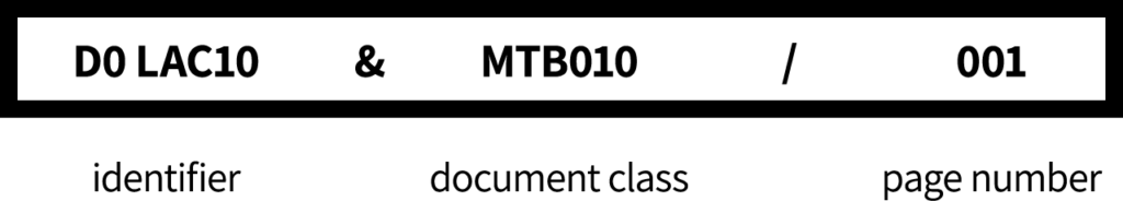
The object identifier usually consists of the function block. The depth of the outline is left to the user in this case. Depending on the document, it is possible to use only the system level but also the complete operating equipment identifier as object identifier. The generally applicable DCC (document type code) of the IEC 61355 series of standards is used to identify the type of document. This series of standards contains both the definition of the identification letters and the various counting specifications.
The last part of the document identifier is used to count different pages of a document.
Application of the marking
According to the combination possibilities of the individual sections of an indicator mentioned at the beginning, various concatenations and assignments of the individual indicator blocks result. A concatenation of one or more blocks always results in a new unique indicator with a defined aspect.
The following table summarizes all permissible linkages of the labeling system.
| Concatenation of the license plate blocks | |||||
| = | Function | – | Product | ||
| = | Function | – | Product | : | Connection |
| = | Function | – | Product | & | Document type |
| = | Function | ; | Name of signal | ||
| = | Function | & | Document type | ||
| == | Functional assignment | ; | Name of signal | ||
| == | Functional assignment | & | Document type | ||
| + | Installation location | & | Document type | ||
| ++ | Installation location | & | Document type | ||
At the heart of the RDS-PP labeling system are the relationships between the individual label blocks. Thus, in addition to the unambiguous identification of the technical objects according to different points of view, a referencing of the markers to marker blocks, which were marked from a different point of view, is also possible.
In contrast to its predecessors, this possibility gives the reference identifier system an object-oriented character, which in turn offers a great advantage in the use of organizational systems. Assignment in this context means the role relations between unique identifiers of the most different aspects.
Bei der Anwendung des Referenzkennzeichensystems RDS-PP stellen die VGB-Richtlinie B101 und die IEC 81346-2 die wichtigsten Regelwerke dar. B101 was developed by a working group of the technical association VGB PowerTech e.V. and contains the letter code of structure level 1 for the indicator blocks Function, Functional assignment, Installation site and Installation location. In the so-called system key, letter combinations, consisting of three letters, are defined with all systems and system boundaries of a power plant.
Since guideline B101 is based on the framework for a classification scheme for infrastructure objects (DIN EN 81346-2), this technical standard is given normative significance. The outline level 2 in the blocks Function, Functional assignment, Installation site and Installation location, respectively both levels of product marking are specified in national and international standards (national: DIN 81346-2 international: IEC 81346-2).
As an aid for the correct application of RDS-PP in practice, the VGB working group published a collection of application explanations in December 2007 (VGB-B116). It contains different application scenarios and solution approaches for the identification of systems in power plants.